

0.7m subsonic open jet wind tunnel
Facility Description
The open jet wind tunnel was designed in the Fall of 2008 by members of the Aerospace & Ocean Engineering faculty and constructed in 2009 in the AOE machine shop. This research quality facility main purpose is to serve as an educational tool for undergraduate instruction.
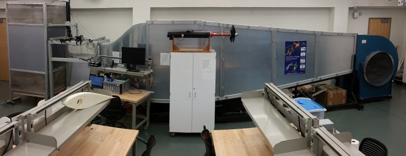
The open-jet wind tunnel is a blower type, open circuit facility shown in Figure 1. A steel frame at the base of the facility provides stability while the combination of aluminum composite panels and extruded aluminum frame results in a light weight yet strong structure. The tunnel is powered by a 30hp BC-SW Size 365 Twin City centrifugal fan capable of up to 15m3/s.
The fan discharges into a 6o, 4m-long diffuser. The flow is then directed into a 1.47m-high by 1.78m-wide settling chamber. A combination of 0.01m-cell size, 0.09m long honeycomb followed by three turbulence reduction screens (made of 0.3mm-diameter fiberglass screen with a 55% open area ratio) ensure a low turbulence and uniform flow. The flow then discharges in the atmosphere through a 5.5:1 contraction nozzle based on a 5th degree polynomial profile.
Flow speed is controlled by an AF-600 General Electric variable frequency drive. At a maximum fan speed of 1180 RPM, the flow exits the 5.5:1 contraction at 30m/s. The flow velocity is measured using static pressure taps located at the exit of the settling chamber. A manometer mounted on the side of the tunnel measures the difference between the settling chamber static pressure and the atmospheric.
To minimize the impact of the flow on the lab environment, the tunnel is equipped with a jet catcher located 1.2m downstream of the contraction exit (as seen in Figure 2). The main purpose of the jet catcher is to deflect and defuse the stream of air. The jet catcher is made of an extruded aluminum frame with composite panels. Two fiberglass high-loss screens inside the catcher deflect the flow towards the ground and ceiling. Further high-loss screens located at the top and bottom of the jet catcher reduce the flow velocity before it enters the room.
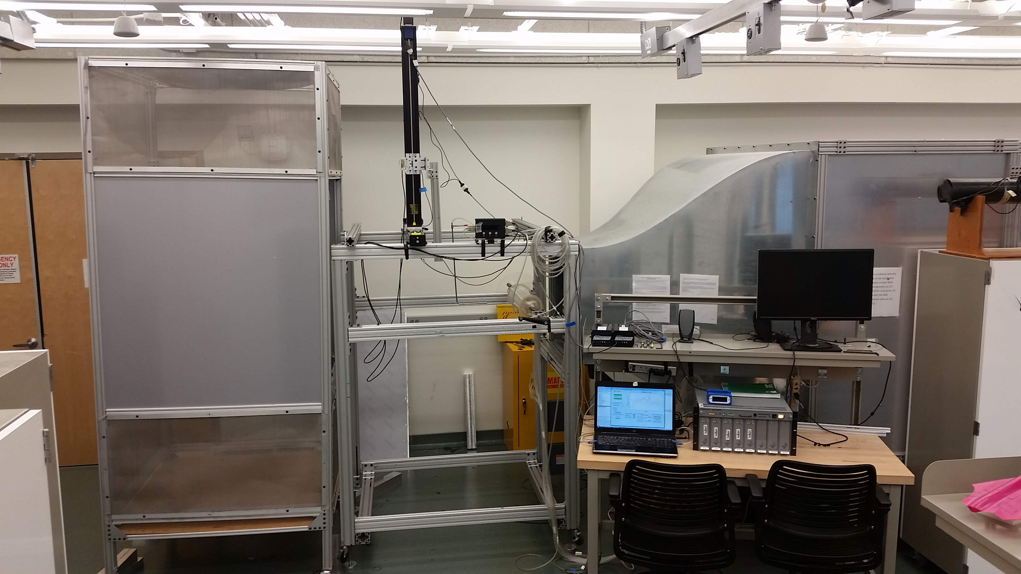
For model mounting, the tunnel is also equipped with an adjustable support frame (show in Figure 2). The frame is built out of extruded aluminum beams. The various slots on these beams provide great flexibility for positioning models.
Contact and Scheduling
The schedule for the open jet wind tunnel is provided below. For more information about the facility capabilities or to schedule wind tunnel time, please complete the proposal template (available here in .docx format) and contact Dr. Aurelien Borgoltz . The proposal is to include detailed information regarding the model shape and dimensions, the details of how it will mount to the tunnel, the type of test you plan on running, what instrumentation is used/needed, and how many test points you aim to complete. Proposals are due at least 1 month before the start date of your test.
Last updated: 2024-01-22 by Aurelien Borgoltz