

Transonic cascade wind tunnel
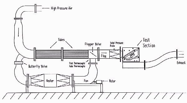
During a run, the upstream total pressure is held constant by varying the opening of a butterfly valve controlled by a computerized feedback circuit. There is also a safety valve upstream of the control valve to start and stop the tunnel. The test section area is 37.3 cm high, and is designed for blades with an outlet angle of approximately 70 degrees. The blade isentropic exit Mach number is varied by changing the upstream total pressure; the usual range for exit Mach number is 0.7 to 1.35. The throat Reynolds number for typical tests is 340,000.
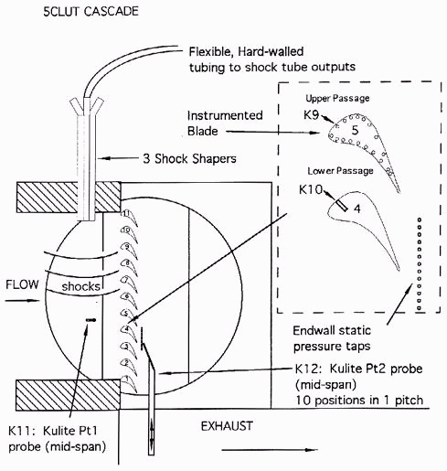
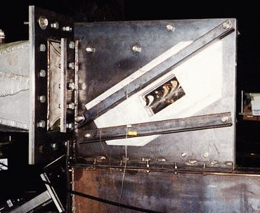
Figure Z is a diagram of the test section. The tunnel mean flow is left to right on the figure, and is turned through 68 degrees by the blade passages, which act as the tunnel throat. Upstream of the blades, the bundle of three shock shapers protrudes from the test section top block; the shocks propagate down from the shaper exit to the bottom of the test section. The high-response total pressure probe for downstream surveys is also shown on the figure, pointing into the cascade exit flow. The probe moves up and down in line with wall static pressure taps. No tailboard is used downstream of the cascade, which means that a free shear layer forms between the exit plane of the blades and the test section back wall. Note also the upstream total pressure probe, which is fixed at mid-pitch of the Lower passage.
Instrumentation
A 30 cm Schlieren apparatus uses two parabolic mirrors and air cooled high pressure mercury lamp. Shadowgraph pictures can be taken either with a direct-shadowgraph system or with a focused shadowgraph arrangement. A 1 microsecond spark source is used for this purpose. Interferograms may be taken with a laser-based single plate interferometer system and a CCD camera.
To record flow phenomena of very rapid action and short time duration, the Hycam high speed motion picture camera can be used. The camera can be optically coupled with either Schlieren or shadowgraph apparatus. Operating speed limits are from 1,000 to 45,000 pictures per second. A six-component force and moment balance is also available.
The main pressure measuring system includes a PSI Model 780B electronically scanned pressure system. The system is IBM PC computer controlled and presently can handle 32 pressure inputs (0 to 1 atm) simultaneously but, if a need arises, it can be expanded up to 512 pressure inputs. Pressure data rate is up to 20,000 measurements per second and the accuracy is 0.1% of span. In addition to the electronically scanned pressure system, there are two Scanivalve systems available, each allowing to record up to 48 pressures (0-3 atm) during a run of a few seconds duration.
Temperature and heat transfer measurements can be made using an automatic multipoint thermocouple reference system and high-speed potentiometric recorders.
Data acquisition is all IBM PC based using modern software such as LabView.