Hypersonic Wind Tunnel
The Virginia Tech hypersonic wind tunnel is a blow-down , high-speed wind tunnel which operates at speeds ranging from Mach 2 to 7. The wind tunnel is owned by the Aerospace & Ocean Engineering department and is part of the PHASE research group.
This blow-down type wind tunnel offers run times on the order of a few seconds at high Mach numbers with relatively steady flow conditions. This facility was obtained through our close and long-term collaborations with the Institute of Theoretical and Applied Mechanics of the Russian Academy of Sciences in Novosibirsk, Russia.
Capabilities
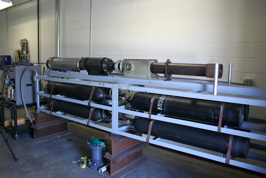
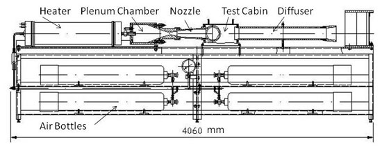
Air (or other working gas) is supplied from a compressor to charge the storage bottles visible within the frame at the bottom. A special fast-acting control valve initiates flow into the plenum chamber. The flow then passes through a contoured, converging-diverging nozzle and out through the diffuser. Due to the working principle of the tunnel and the fast-acting control valve, there is only a slow decrease in total pressure during the run. The variation of the total pressure during the run is in the range of approximately 10%. For Mach numbers above 4, an electric heater raises the total temperature up to 800 K to prevent liquefaction. The nozzle exit diameter is 100 mm. The test cabin arrangement permits the use of relatively large instream models, especially at the higher Mach numbers. Working gases include air, nitrogen, argon, helium.
This facility can be used for aerodynamic problem investigations which involve proper values of Mach and Reynolds number, to try out new measurement methods in high-speed flows, and for laboratory instruction of students.
Other Specifications
- The total mass of storage air in 8x40 dm 3 bottles with pressure of 150 bars is 56 kg. Each run uses about 2.7 kg/s of pressurized gas. It is possible that standard bottles or a high-pressure compressor with low delivery (capacity) will be used as a working gas supply.
- The upper limit of stagnation pressure in the storage bottles is Pb = 15 MPa.
- The upper limit of stagnation temperature is To = 800 K.
- Test section size is 100mm.
- Electric heater (220/380 V) with capacity 15 - 20 kW provides the flow stagnation temperature up to 800 K to prevent condensation of air at hypersonic speeds.
- Tested models usually have the length 200 - 300 mm at the angle of attack 00 - 100 and 80 - 120 mm at the angle attack up to 400 - 500. The diameter of tested models is 20 - 40 mm.
- Inner dimensions of test chamber are 360 x 226 x 200 mm.
- Run duration depends on the test conditions and is usually from 1.0 to 2.0 s. During this time the flow stagnation pressure and temperature decrease smoothly nevertheless relative flow parameters and Mach number keep their constant values.
- Axisymmetric replaceable contoured nozzles are fitted to the flange of a settling chamber.